Board Mapping
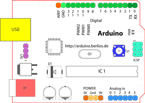
The physical layout and pins of an Arduino Uno look as follows:
while an Pi header looks as follows:

The mappings selected are as close to 1-to-1 mappings as possible.
The Arduino Dx pin corresponds to the Pi GPIOx pin. For example, a write to Arduino D1 produces a signal on Pi GPIO1. There are some caveats:
- Sketches should not write to D0 as there is no GPIO0 on the Pi.
- Sketches should not read or write to A0-A5 as there is no analog input or output on the Pi.
- Some Pi Pins have special functions that would conflict with Arduino logical pins, for example:
- I2C in a sketch will use D2/D3 (GPIO2/GPIO3)
- UART on the Pi appears at D14/D15 (GPIO14/GPIO15) as opposed to D1/D0 on the Arduino